I have gathered 3 tutorials about the Acer Aspire One series of netbooks which I have found to be incredibly useful. These units are a nice compact design but they have their own share of drawbacks which without a proper fix can make these a very fraustrating purchase. These tutorials were not written by myself however, I have credited the authors providing a link to their sites. I have reposted here for convenience.
Thanks for reading.
Brokenmachine
Acer One AOA110 and AOA150 netbooks have a common problem which I first encountered in 2009 where the unit powers up but the screen stays black and the unit doesn't start.
I came across a post at http://impormasyon.info which had the specific instructions required to repair this problem. After following the instructions step-by-step the netbook started up perfectly.
The information is fairly dated but I feel that it is still a relevent repair issue as I continue to see these units trickle in even 1 year later.
Reposted from http://impormasyon.info/tag/acer-aspire-one-aoa-110-power-on-but-screen-remain-blank/
•The first thing you need to prepare USB Flash Driver. You need to use flash drive to store the BIOS information on during the update procedure.
•The next thing you need to do is download the latest BIOS for the netbook. If you don’t where you can find that BIOS then click here. Under the link I gave to you choose NETBOOK>ASPIRE ONE>AOA110>BIOS.
•After you downloaded the file, extract it , and inside the extracted folder open “DOS_Flash folder” rename the BIOS file from 3310.fd to zg5ia32.fd.
•Copy zg5ia32.fd and Flashit.exe to USB Flash Drive
•Insert your USB Flash Drive into a USB port.
•Press and Hold down the FN and ESC keys together and press the power button. Make sure that your AC Adapter is plugged in.
•Once the unit’s power light comes on wait ON, wait a few seconds and release the FN and ESC keys.
•After the keys have been released , the power light will start to blink and also start the process of BIOS update. But the display will still remain blank in the process of updating.
•Just let the unit run and after 1 to 7 minutes approximately, the unit should reboot and the BIOS will be updated. If the unit fails to reboot or the BIOS was not updated successfully, try the steps again and make sure you download the right BIOS file.
Note: These instructions are only for the Acer Aspire One AOA-110 and AOA-150 netbook series and shouldn’t be performed on any other model Acer Aspire One.
If all goes well you should have succeeded in bringing your Acer One netbook back from the dead!
*****
Next, Maybe a little more memory or a larger hard drive (Hard Drive model ONLY)
These instructions were obtained from http://www.dalekeller.net/ the instructions were made into a .pdf file and they make upgrading an Acer One netbook really easy!
Reposted from http://www.dalekeller.net/Other/Computers/AspireOne/Disassembly.pdf
Acer Aspire One AOA150-1570 Disassembly
Model
•The Acer Aspire One AOA150-1570 is the model with the 120GB hard drive (not the Flash drive) and 1GB RAM with Windows XP.
Disassembly
•Beware of the ESD (ElectroStatic Discharge) hazard. Wear a grounding wrist strap.
•Remove the battery.
•Remove the 6 screws from the bottom of the case. There are 3 across the front and 3 in the battery compartment.
•Pry up the 2 rear rubber feet and remove the 2 screws underneath them. Stick the feet to the battery for safekeeping.
 |
| Bottom of machine with locations of screws marked |
Note: The 3 short screws go in the battery compartment.
•Remove the keyboard. There are 3 locking tabs at the top of the keyboard, in the top cover, sticking out over the edge of the keyboard. Press them toward the back of the machine with a small flat screwdriver. Gently pry the keyboard up from the top. Be careful not to pop off any keycaps. There are small nibs holding it in place on the sides, and they will resist removal. Be careful of the keyboard cable.
 |
| Keyboard locking tabs |
•When the keyboard comes up, disconnect the keyboard cable by gently pulling up on the right edge of the black cable lock (near the blue part of the cable). When it rotates up, the cable can be pulled free. Lift out the keyboard.
 |
| Keyboard cable connector |
•Disconnect the touchpad cable, which is a smaller version of the keyboard connector, by lifting the black lock mechanism.
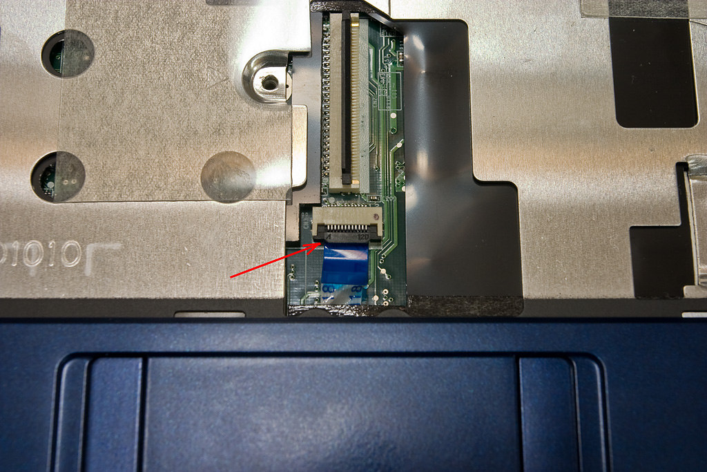 |
| Touchpad cable connector |
•Remove the 6 screws holding the top cover down. Keep track of which screws go where. There are some different sizes.
 |
| Screw locations in top cover |
•There are also locking tabs around the edge of the top cover. You will have to pry it up to get it started.
Remove the top cover by tilting up the touchpad end and pulling it toward you. Again, take note of which screws go where.
•Remove the 1 screw holding the wireless card (the small board in the front). Tilt the wireless card up and remove it from its socket. You do not need to disconnect the antenna wires.
•Remove the 1 screw holding the mainboard (the large board on the left).
•Remove the 3 screws holding the I/O card (the narrow board on the right).
•Slowly pull up the yellow tape holding the speaker cable (speedy separation = ESD hazard). Disconnect the speaker cable (the one coming up from the front). It can be pretty tight. Rock it gently.
 |
| Main board, I/O board, and WIFI card screw locations, and speaker cable connector |
•Lift the I/O card and the WIFI card out of the way. Lift the front edge of the mainboard and pull it toward you to get it out from under the left rear tab (under the LCD cable). The hard drive will come with it. You can leave the LCD cable in place (the wide ribbon at the left rear). Flip them over.
 |
| Boards flipped over |
•On the back of the mainboard you will find the RAM socket and the Hard Disk.
•The 120GB SATA hard drive is attached to the mainboard with 2 screws. It is also enclosed in a shell attached with 4 screws.
 |
| Hard drive enclosure with attaching screws, and RAM socket |
•If you are changing the hard drive, remove the 2 screws holding the enclosure in place, and then pull the drive from the SATA socket. Remove the 4 screws holding the enclosure to the drive.
•If you are adding RAM, the socket is easily accessible. This computer has 512MB soldered to the top of the board and a 512MB SODIMM in the socket on the bottom of the board.
Just for Information
•The RAM looks like this.
 |
| The RAM stick |
•The Hard Drive looks like this.
 |
| The hard drive and its enclosure |
Reassembly
•Assembly is the exact reverse of the disassembly procedure, but with a couple of cautions.
When you replace the mainboard be sure to slip it UNDER the clip at the left rear under the LCD cable.
 |
| Metal clip over mainboard, and LCD cable |
•Once the mainboard is in place, tuck the LCD cable back down into its spot.
•Bring the speaker cable up over the front of the mainboard. Reconnect it and then put the yellow tape back in place.
•When reinstalling the WIFI board, reroute the antenna wires into their proper place so they don’t interfere with anything else. See the photo in the disassembly section above.
•When reinstalling the I/O board, carefully align the WIFI switch to sit in the switch extender.
 |
| WIFI switch (white tab) sitting in switch extender (black channel) |
•When replacing the top cover, tilt the back down so it will slip under the LCD hinges. Lower the front into place. There are small tabs all around the cover which help hold it in place. Be sure these tabs all latch into place before screwing it down. Look at the photos shown in the disassembly section for the screw locations.
•When reinstalling the touchpad and keyboard cables, make sure the cable seats all the way into position before lowering the black lock bar.
•When reinstalling the keyboard place the spacebar edge of the keyboard in place first. It has tabs which must go under the edge before the rest of the keyboard can drop into place. Gently press the top of the keyboard down until the 3 latching tabs pop into place.
•When reinstalling the screws on the bottom, the short ones go in the battery compartment.
Don’t forget to get the feet from where you stored them (on the battery, perhaps) and put them back in place.
*****
Finally, for those Acer Netbooks out there with the teenie-tiny Nand SSD Drive installed, check FlashFire out! This program rocks! I have tested this software with an Acer One AOA110 netbook running Windows XP 32-bit. It transformed a netbook which took the better part of 10 minutes to boot into an actual computer (which could then suprisingly run Open Office. It uses host RAM to enhance random write performance on low-end SSDs. The program is incredible and is well worth checking out.
*****
No comments:
Post a Comment